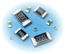
The selection of resistors requires comprehensive consideration of circuit performance, environmental conditions, and cost factors. The following are the core selection logic and standards:

Basic parameter matching
Resistance range: Select based on circuit calculation values, with priority given to E24/E96 standard sequence values to avoid cost increases caused by non-standard customization.
Precision tolerance:
Universal circuits (such as LED current limiting) can choose ± 5%;
Precision voltage divider/ADC reference circuit requires ± 1% or higher;
Special scenarios (such as medical equipment) can use ± 0.1% precision resistors.
Power margin: The actual power consumption should be less than 50% and 70% of the rated power (for example, if the power consumption in the circuit is 0.5W, it is recommended to choose a resistor with more than 1W) to avoid the risk of high temperature derating.
Environmental Adaptability Design
Temperature coefficient (TCR):
Conventional scenario: ± 200ppm/℃;
Wide temperature range equipment (55 ℃~125 ℃): metal film resistor (± 50ppm/℃) or thick film resistor;
Extreme temperature drift sensitive circuit: Choose wound resistors (± 10ppm/℃) or foil resistors (± 1ppm/℃).
Voltage resistance and insulation: High voltage circuits (such as power input stages) need to verify the rated voltage of the resistance (such as 1206 package voltage resistance of 200V) to avoid breakdown caused by insufficient creepage distance.
Mechanical strength: Surface mount resistors or epoxy coated wire wound resistors are preferred for vibration environments to avoid lead breakage.
Functional feature enhancement
High frequency characteristics:
Select thin film resistors (parasitic inductance<1nH) for RF circuits;
Avoid using wire wound resistors (parasitic inductance can reach tens of nH).
Anti pulse capability: For power surge protection, anti pulse thick film resistors or metal oxide resistors should be selected to withstand instantaneous high currents.
Low noise design: High sensitivity circuits such as preamplifiers use metal foil resistors (noise<40dB) to avoid 1/f noise from carbon film resistors.
Packaging and process adaptation
PCB layout compatibility:
0402/0201 patch for high-density board;
Choose TO220 package or add heat sink for high-power scenarios;
Choose long body packaging (such as 2512 patch) for high-voltage isolation scenarios.
Welding process:
Optimal axial lead resistance for wave soldering;
Reflow soldering requires confirmation of the resistance temperature resistance curve (such as thick film resistance to 260 ℃/10s).
Cost and supply chain balance
Cost effectiveness rating:
Consumer electronics: carbon film/thick film resistors (unit price<¥ 0.01);
Industrial grade: Metal film resistor (¥ 0.05~0.5);
Military regulations/Aerospace: Precision foil resistors (¥ 10-100+).
Supply cycle: Avoid using obscure resistors or packaging, prioritize manufacturer standard products (such as Guoju, Vishay, and other top brands' regular inventory).
Selection decision tree
Determine circuit requirements (resistance, power, accuracy) →
Analyze environmental stress (temperature, humidity, vibration) →
Filter functional characteristics (high frequency/anti pulse/low noise) →
Matching packaging and process →
Assessing costs and supply risks →
Validate samples (temperature drift test, long-term aging experiment).
By systematically balancing the above elements, circuit failure caused by a single parameter omission can be avoided, and design reliability can be improved.
